

Lihat spesifikasi untuk butiran produk.
IRF614L
Product Overview
Category: Power MOSFET
Use: Switching applications
Characteristics: High voltage, low on-resistance
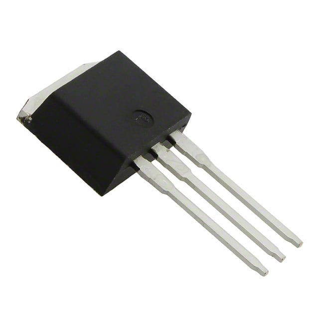
Package: TO-220AB
Essence: Power transistor for high-speed switching applications
Packaging/Quantity: Bulk packaging, quantity varies
Specifications
- Voltage Rating: 250V
- Continuous Drain Current: 3.3A
- On-Resistance: 0.75Ω
- Pulse Current: 13A
- Gate Threshold Voltage: 2V to 4V
- Power Dissipation: 94W
Detailed Pin Configuration
The IRF614L comes in a TO-220AB package with three pins: 1. Gate (G): Input terminal for controlling the flow of current. 2. Drain (D): Output terminal through which the current flows out. 3. Source (S): Terminal connected to the ground reference.
Functional Features
- Fast switching speed
- Low gate drive power
- Avalanche energy specified
- Improved dv/dt capability
Advantages and Disadvantages
Advantages: - Low on-resistance - High input impedance - Good thermal stability - High input capacitance
Disadvantages: - Susceptible to damage from overvoltage spikes - Sensitivity to static electricity
Working Principles
The IRF614L operates based on the principle of field-effect transistors. When a voltage is applied to the gate terminal, it creates an electric field that controls the flow of current between the drain and source terminals. This allows for efficient switching of high-power loads.
Detailed Application Field Plans
The IRF614L is commonly used in various applications such as: - Switch mode power supplies - DC-DC converters - Motor control - Inverters - Electronic ballasts
Detailed and Complete Alternative Models
- IRF610: Similar characteristics, lower voltage rating
- IRF620: Higher voltage rating, similar on-resistance
- IRF630: Higher continuous drain current, similar voltage rating
In conclusion, the IRF614L is a versatile power MOSFET suitable for high-speed switching applications. Its high voltage rating, low on-resistance, and fast switching speed make it an ideal choice for various power electronics applications.
Word count: 298
Senaraikan 10 soalan dan jawapan biasa yang berkaitan dengan aplikasi IRF614L dalam penyelesaian teknikal
What is the IRF614L transistor used for?
- The IRF614L is a power MOSFET transistor commonly used in high-power switching applications such as motor control, power supplies, and inverters.
What are the key specifications of the IRF614L?
- The IRF614L has a maximum drain-source voltage of 250V, a continuous drain current of 3.3A, and a low on-resistance for efficient power handling.
How do I properly drive the IRF614L in my circuit?
- To drive the IRF614L effectively, ensure that the gate voltage is within the specified range (typically around 10V) to fully turn on the transistor and minimize switching losses.
Can the IRF614L be used for PWM (Pulse Width Modulation) applications?
- Yes, the IRF614L is suitable for PWM applications due to its fast switching characteristics and low on-resistance, making it ideal for controlling power to loads.
What are the thermal considerations when using the IRF614L?
- Proper heat sinking is essential when using the IRF614L to dissipate the heat generated during operation, ensuring that the junction temperature stays within safe limits.
Are there any common failure modes associated with the IRF614L?
- Common failure modes include overvoltage or overcurrent conditions leading to excessive heating, which can cause the transistor to fail if not properly managed.
Can the IRF614L be used in automotive applications?
- Yes, the IRF614L is suitable for automotive applications, provided that it meets the necessary automotive-grade specifications and requirements.
What are the typical applications where the IRF614L is commonly used?
- The IRF614L is often used in applications such as motor drives, DC-DC converters, uninterruptible power supplies (UPS), and industrial power systems.
How do I protect the IRF614L from voltage spikes and transients?
- Using appropriate snubber circuits, freewheeling diodes, and transient voltage suppressors can help protect the IRF614L from voltage spikes and transients.
What are some best practices for PCB layout when using the IRF614L?
- Ensure short and direct traces for gate drive connections, proper placement of decoupling capacitors, and adequate copper area for heat dissipation to optimize performance and reliability.