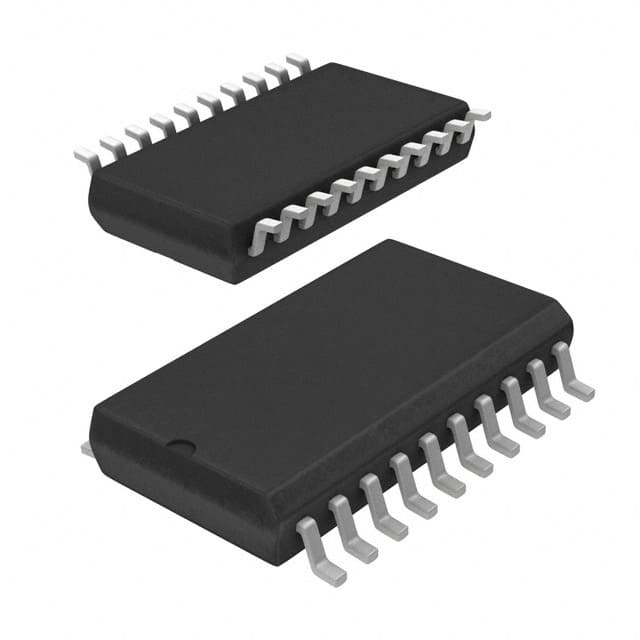
SN74HCT541DWRE4
Product Overview
- Category: Integrated Circuit
- Use: Buffer/Line Driver
- Characteristics: High-speed, CMOS compatible, 3-state outputs
- Package: SOIC (Small Outline Integrated Circuit)
- Essence: A high-performance octal buffer/line driver with 3-state outputs
- Packaging/Quantity: Tape and Reel, 2500 pieces per reel
Specifications
- Supply Voltage Range: 2V to 6V
- Input Voltage Range: 0V to VCC
- Output Voltage Range: 0V to VCC
- Maximum Operating Frequency: 74 MHz
- Number of Channels: 8
- Output Current: ±6 mA
- Propagation Delay Time: 13 ns (max)
- Operating Temperature Range: -40°C to +85°C
Pin Configuration
The SN74HCT541DWRE4 has a total of 20 pins. The pin configuration is as follows:
- GND (Ground)
- A1 (Input A1)
- B1 (Input B1)
- Y1 (Output Y1)
- A2 (Input A2)
- B2 (Input B2)
- Y2 (Output Y2)
- A3 (Input A3)
- B3 (Input B3)
- Y3 (Output Y3)
- A4 (Input A4)
- B4 (Input B4)
- Y4 (Output Y4)
- VCC (Supply Voltage)
- OE (Output Enable)
- Y5 (Output Y5)
- A5 (Input A5)
- B5 (Input B5)
- Y6 (Output Y6)
- A6 (Input A6)
Functional Features
- Octal buffer/line driver with 3-state outputs
- High-speed operation suitable for various applications
- CMOS compatible inputs for easy interfacing with other devices
- Output enable (OE) pin for controlling the output state
- Low power consumption
Advantages and Disadvantages
Advantages: - High-speed operation allows for efficient data transfer - CMOS compatibility ensures easy integration with other devices - 3-state outputs provide flexibility in bus systems - Low power consumption helps conserve energy
Disadvantages: - Limited output current may not be suitable for high-power applications - Propagation delay time may affect timing-sensitive operations
Working Principles
The SN74HCT541DWRE4 is designed to buffer and drive signals in digital systems. It takes input signals from the A1-A6 and B1-B5 pins and provides corresponding output signals on the Y1-Y6 pins. The output enable (OE) pin controls the output state, allowing the device to be easily enabled or disabled.
When the OE pin is low, the outputs are active and follow the input signals. When the OE pin is high, the outputs are in a high-impedance state, effectively disconnecting them from the rest of the circuit.
Detailed Application Field Plans
The SN74HCT541DWRE4 is commonly used in various applications, including:
- Data communication systems
- Microprocessor-based systems
- Memory address drivers
- Bus interface buffers
- Clock distribution networks
- Industrial control systems
- Automotive electronics
- Consumer electronics
Detailed and Complete Alternative Models
Some alternative models that can be considered as replacements for the SN74HCT541DWRE4 include:
- SN74LS541: Low-power Schottky version with similar functionality
- SN74ACT541: Advanced CMOS version with faster switching speeds
- SN74HC541: Standard CMOS version with comparable characteristics
These alternative models offer similar features and can be used as drop-in replacements in many applications.
Word count: 314 words
Senaraikan 10 soalan dan jawapan biasa yang berkaitan dengan aplikasi SN74HCT541DWRE4 dalam penyelesaian teknikal
Sure! Here are 10 common questions and answers related to the application of SN74HCT541DWRE4:
Question: What is the SN74HCT541DWRE4?
Answer: The SN74HCT541DWRE4 is a high-speed octal buffer/line driver with 3-state outputs.Question: What is the operating voltage range for this device?
Answer: The operating voltage range for the SN74HCT541DWRE4 is 4.5V to 5.5V.Question: What is the maximum output current that this device can handle?
Answer: The maximum output current for each channel of the SN74HCT541DWRE4 is ±6mA.Question: Can I use this device for level shifting applications?
Answer: Yes, the SN74HCT541DWRE4 can be used for level shifting between different voltage domains.Question: What is the typical propagation delay of this device?
Answer: The typical propagation delay for the SN74HCT541DWRE4 is 11ns.Question: Does this device have internal pull-up or pull-down resistors?
Answer: No, the SN74HCT541DWRE4 does not have internal pull-up or pull-down resistors.Question: Can I use this device in bidirectional communication?
Answer: No, the SN74HCT541DWRE4 is a unidirectional buffer and cannot be used for bidirectional communication.Question: What is the maximum operating frequency for this device?
Answer: The maximum operating frequency for the SN74HCT541DWRE4 is 50MHz.Question: Is this device compatible with TTL logic levels?
Answer: Yes, the SN74HCT541DWRE4 is compatible with both TTL and CMOS logic levels.Question: Can I use this device in automotive applications?
Answer: Yes, the SN74HCT541DWRE4 is qualified for automotive applications and meets the AEC-Q100 standard.
Please note that these answers are general and may vary depending on specific application requirements. It's always recommended to refer to the device datasheet and consult the manufacturer for detailed information.


