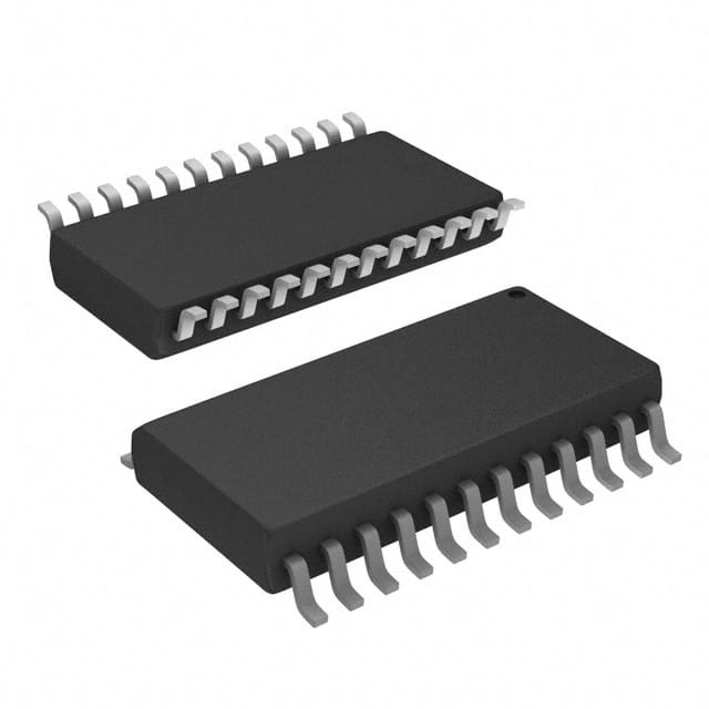
SN74ALS654DWR
Product Overview
- Category: Integrated Circuit (IC)
- Use: Logic Function
- Characteristics: High-speed, low-power consumption
- Package: SOIC (Small Outline Integrated Circuit)
- Essence: 8-bit bus transceiver with 3-state outputs
- Packaging/Quantity: Tape and Reel, 2500 units per reel
Specifications
- Supply Voltage Range: 4.5V to 5.5V
- Input Voltage Range: 0V to VCC
- Output Voltage Range: 0V to VCC
- Operating Temperature Range: -40°C to +85°C
- Propagation Delay Time: 6ns (typical)
- Output Current: ±24mA
- Number of Pins: 20
Detailed Pin Configuration
- A0 - Data Input/Output Bit 0
- A1 - Data Input/Output Bit 1
- A2 - Data Input/Output Bit 2
- A3 - Data Input/Output Bit 3
- A4 - Data Input/Output Bit 4
- A5 - Data Input/Output Bit 5
- A6 - Data Input/Output Bit 6
- A7 - Data Input/Output Bit 7
- OE - Output Enable
- DIR - Direction Control
- GND - Ground
- B7 - Data Input/Output Bit 7
- B6 - Data Input/Output Bit 6
- B5 - Data Input/Output Bit 5
- B4 - Data Input/Output Bit 4
- B3 - Data Input/Output Bit 3
- B2 - Data Input/Output Bit 2
- B1 - Data Input/Output Bit 1
- B0 - Data Input/Output Bit 0
- VCC - Supply Voltage
Functional Features
- Bidirectional data transfer between two buses
- 3-state outputs for bus isolation
- Output enable and direction control for flexible operation
- High-speed operation suitable for demanding applications
- Low-power consumption for energy efficiency
Advantages and Disadvantages
Advantages: - Allows efficient data exchange between different buses - Provides flexibility in controlling data flow with output enable and direction control pins - High-speed operation ensures quick data transfer - Low-power consumption reduces energy usage
Disadvantages: - Limited to 8-bit data transfer, may not be suitable for larger data sizes - Requires careful handling due to sensitive integrated circuitry
Working Principles
The SN74ALS654DWR is an 8-bit bus transceiver that enables bidirectional data transfer between two buses. It features 3-state outputs, which allow the device to isolate itself from the bus when necessary. The output enable (OE) pin controls the state of the outputs, while the direction (DIR) pin determines the data flow direction.
When OE is high, the outputs are enabled, and data can be transferred bidirectionally between the A and B buses. When OE is low, the outputs are disabled, effectively isolating the device from the bus. The DIR pin determines the direction of data flow: when DIR is low, data flows from A to B, and when DIR is high, data flows from B to A.
Detailed Application Field Plans
The SN74ALS654DWR is commonly used in various applications where bidirectional data transfer is required. Some specific application fields include:
- Microprocessor Systems: The IC facilitates communication between the microprocessor and other peripherals, such as memory modules or input/output devices.
- Data Communication Networks: It enables data exchange between different network nodes, ensuring efficient and reliable communication.
- Industrial Automation: The IC can be used in control systems to transfer data between different components, such as sensors, actuators, and controllers.
- Automotive Electronics: It plays a crucial role in automotive electronics, allowing data transfer between various subsystems, such as engine control units, infotainment systems, and sensors.
Detailed and Complete Alternative Models
- SN74ALS652A: Similar to SN74ALS654DWR but with 6-bit bus transceiver functionality.
- SN74ALS655: 8-bit bus transceiver with additional parity generation/checking capability.
- SN74ALS651: 8-bit bus transceiver with open-drain outputs for wired-OR applications.
These alternative models offer similar functionality with slight variations to cater to specific requirements.
Word count: 550 words
Senaraikan 10 soalan dan jawapan biasa yang berkaitan dengan aplikasi SN74ALS654DWR dalam penyelesaian teknikal
Sure! Here are 10 common questions and answers related to the application of SN74ALS654DWR:
Q: What is SN74ALS654DWR? A: SN74ALS654DWR is a specific type of integrated circuit (IC) commonly used in technical solutions for signal switching and multiplexing applications.
Q: What is the function of SN74ALS654DWR? A: SN74ALS654DWR is a 16-channel digital multiplexer/demultiplexer IC that allows for the selection of one input from multiple sources and routing it to an output.
Q: What voltage levels does SN74ALS654DWR support? A: SN74ALS654DWR supports a wide range of voltage levels, typically between 4.5V and 5.5V.
Q: How many inputs can SN74ALS654DWR handle? A: SN74ALS654DWR can handle up to 16 inputs, making it suitable for applications requiring multiple signal sources.
Q: Can SN74ALS654DWR be used for bidirectional signal routing? A: No, SN74ALS654DWR is a unidirectional multiplexer/demultiplexer and does not support bidirectional signal routing.
Q: What is the maximum frequency at which SN74ALS654DWR can operate? A: SN74ALS654DWR can operate at frequencies up to 25 MHz, making it suitable for various high-speed applications.
Q: Does SN74ALS654DWR have any built-in protection features? A: Yes, SN74ALS654DWR has built-in electrostatic discharge (ESD) protection on all inputs and outputs, ensuring reliability in harsh environments.
Q: Can SN74ALS654DWR be cascaded to increase the number of inputs? A: Yes, multiple SN74ALS654DWR ICs can be cascaded together to increase the number of inputs and achieve more complex signal routing.
Q: What is the power supply requirement for SN74ALS654DWR? A: SN74ALS654DWR requires a single power supply voltage between 4.5V and 5.5V for proper operation.
Q: Are there any specific considerations for PCB layout when using SN74ALS654DWR? A: Yes, it is recommended to follow the manufacturer's guidelines for PCB layout, including proper decoupling capacitors placement and minimizing trace lengths to reduce noise and ensure signal integrity.
Please note that these answers are general and may vary depending on the specific application and requirements. It is always advisable to refer to the datasheet and consult with technical experts for accurate information.


