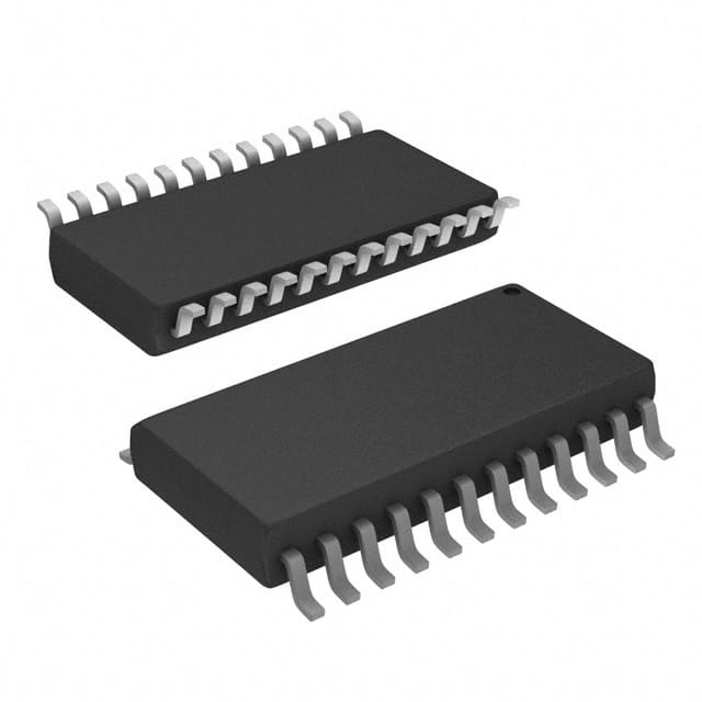
SN74ALS654DW
Product Overview
- Category: Integrated Circuit (IC)
- Use: Digital Logic
- Characteristics: High-speed, low-power, 8-bit bus transceiver
- Package: SOIC (Small Outline Integrated Circuit)
- Essence: Transfers data bidirectionally between two buses
- Packaging/Quantity: Tape and Reel, 2500 units per reel
Specifications
- Supply Voltage Range: 4.5V to 5.5V
- Input Voltage Range: 0V to VCC
- Output Voltage Range: 0V to VCC
- Operating Temperature Range: -40°C to +85°C
- Propagation Delay Time: 6ns (typical)
- Output Drive Capability: ±24mA
Detailed Pin Configuration
The SN74ALS654DW has a total of 20 pins. The pin configuration is as follows:
- A0: Data Bus A Bit 0
- A1: Data Bus A Bit 1
- A2: Data Bus A Bit 2
- A3: Data Bus A Bit 3
- A4: Data Bus A Bit 4
- A5: Data Bus A Bit 5
- A6: Data Bus A Bit 6
- A7: Data Bus A Bit 7
- GND: Ground
- OE*: Output Enable (Active Low)
- DIR: Direction Control
- B7: Data Bus B Bit 7
- B6: Data Bus B Bit 6
- B5: Data Bus B Bit 5
- B4: Data Bus B Bit 4
- B3: Data Bus B Bit 3
- B2: Data Bus B Bit 2
- B1: Data Bus B Bit 1
- B0: Data Bus B Bit 0
- VCC: Supply Voltage
Functional Features
- Bidirectional data transfer between two buses (A and B)
- Output enable control for tristate operation
- Direction control to select the direction of data flow
- High-speed operation with low power consumption
- TTL-compatible inputs and outputs
Advantages and Disadvantages
Advantages: - High-speed data transfer - Low power consumption - Tristate output capability - Wide operating temperature range
Disadvantages: - Limited voltage supply range (4.5V to 5.5V) - Requires external control signals for proper operation
Working Principles
The SN74ALS654DW is a bidirectional bus transceiver that allows data transfer between two separate buses, A and B. The direction of data flow is controlled by the DIR pin. When DIR is high, data flows from bus A to bus B, and when DIR is low, data flows from bus B to bus A.
The OE* pin is used to enable or disable the outputs. When OE* is low, the outputs are enabled and actively drive the bus lines. When OE* is high, the outputs are disabled and enter a high-impedance state, allowing other devices to drive the bus lines.
Detailed Application Field Plans
The SN74ALS654DW is commonly used in various digital logic applications, including:
- Microprocessor-based systems
- Data communication systems
- Industrial control systems
- Automotive electronics
- Test and measurement equipment
Detailed and Complete Alternative Models
- SN74ALS652A: 8-bit bus transceiver with inverted outputs
- SN74ALS653: 8-bit bus transceiver with parity generator/checker
- SN74ALS655: 8-bit bus transceiver with output registers
These alternative models provide similar functionality to the SN74ALS654DW but may have additional features or variations in specifications.
Word count: 440 words
Senaraikan 10 soalan dan jawapan biasa yang berkaitan dengan aplikasi SN74ALS654DW dalam penyelesaian teknikal
Sure! Here are 10 common questions and answers related to the application of SN74ALS654DW:
Q: What is SN74ALS654DW? A: SN74ALS654DW is a specific type of integrated circuit (IC) commonly used in technical solutions for various applications.
Q: What is the purpose of SN74ALS654DW? A: SN74ALS654DW is a 16-bit decoder/demultiplexer IC that can be used to decode binary information and control multiple output lines based on the input signals.
Q: What voltage levels does SN74ALS654DW support? A: SN74ALS654DW supports a wide range of voltage levels, typically between 4.5V and 5.5V.
Q: How many output lines can SN74ALS654DW control? A: SN74ALS654DW can control up to 16 output lines, making it suitable for applications requiring multiple outputs.
Q: Can SN74ALS654DW be used in both digital and analog applications? A: No, SN74ALS654DW is primarily designed for digital applications and may not be suitable for analog applications.
Q: What is the maximum frequency at which SN74ALS654DW can operate? A: SN74ALS654DW can operate at frequencies up to several megahertz, depending on the specific application and conditions.
Q: Are there any special considerations for power supply requirements? A: SN74ALS654DW requires a stable power supply within the specified voltage range to ensure proper operation.
Q: Can SN74ALS654DW be cascaded to control more than 16 output lines? A: Yes, multiple SN74ALS654DW ICs can be cascaded together to control a larger number of output lines.
Q: What are some typical applications of SN74ALS654DW? A: SN74ALS654DW can be used in various applications such as address decoding, data routing, multiplexing, and demultiplexing.
Q: Where can I find more information about the specifications and usage of SN74ALS654DW? A: The datasheet provided by the manufacturer is the best source for detailed information on the specifications and usage of SN74ALS654DW.


