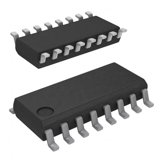
CD40147BM
Product Overview
- Category: Integrated Circuit
- Use: BCD-to-Seven Segment Decoder/Driver
- Characteristics: High Voltage, High Current Capability, Low Power Consumption
- Package: 16-pin DIP (Dual In-line Package)
- Essence: Converts Binary-Coded Decimal (BCD) input to a 7-segment display output
- Packaging/Quantity: Available in tubes of 25 units or reels of 1000 units
Specifications
- Supply Voltage: 3V to 18V
- Input Voltage: 0V to VDD
- Output Voltage: 0V to VDD
- Operating Temperature Range: -55°C to +125°C
- Maximum Power Dissipation: 500mW
Detailed Pin Configuration
- A0 - BCD Input Bit 0
- A1 - BCD Input Bit 1
- A2 - BCD Input Bit 2
- A3 - BCD Input Bit 3
- LT - Lamp Test Input
- BI/RBO - Blanking Input/ Ripple Blanking Output
- RBI - Ripple Blanking Input
- a - Seven Segment Output a
- b - Seven Segment Output b
- c - Seven Segment Output c
- d - Seven Segment Output d
- e - Seven Segment Output e
- f - Seven Segment Output f
- g - Seven Segment Output g
- VSS - Ground
- VDD - Supply Voltage
Functional Features
- Converts BCD input to a 7-segment display output
- Supports lamp test and blanking functions
- Ripple blanking input for cascading multiple devices
- High voltage and high current capability
- Low power consumption
Advantages
- Versatile and widely used in digital display applications
- Can drive common anode or common cathode displays
- Supports cascading for larger displays
- Wide operating voltage range allows flexibility in power supply selection
Disadvantages
- Limited to BCD input, not suitable for other numeric systems
- Requires additional components for driving multiplexed displays
- Not suitable for high-speed applications due to propagation delay
Working Principles
The CD40147BM is a BCD-to-Seven Segment Decoder/Driver integrated circuit. It takes a 4-bit Binary-Coded Decimal (BCD) input and converts it into the appropriate signals to drive a 7-segment display. The inputs A0-A3 represent the BCD digits, while the outputs a-g control the segments of the display.
The IC also features additional inputs such as Lamp Test (LT), Blanking Input/Ripple Blanking Output (BI/RBO), and Ripple Blanking Input (RBI). These inputs allow for testing the display, blanking segments, and cascading multiple devices for larger displays.
Detailed Application Field Plans
The CD40147BM is commonly used in various applications that require BCD-to-7 segment decoding. Some typical application fields include:
- Digital clocks and timers
- Counters and frequency meters
- Industrial control panels
- Instrumentation displays
- Scoreboards and score displays
- Electronic voting machines
Detailed and Complete Alternative Models
- CD4511B - BCD-to-7 Segment Latch/Decoder/Driver
- SN74LS47 - BCD-to-7 Segment Decoder/Driver
- HEF4543B - BCD-to-7 Segment Latch/Decoder/Driver
- MM74C48 - BCD-to-7 Segment Decoder/Driver
These alternative models offer similar functionality and can be used as replacements for the CD40147BM in various applications.
In conclusion, the CD40147BM is a versatile BCD-to-Seven Segment Decoder/Driver integrated circuit. It offers high voltage and current capability while consuming low power. With its wide range of applications and availability of alternative models, it is a popular choice for digital display projects.
Senaraikan 10 soalan dan jawapan biasa yang berkaitan dengan aplikasi CD40147BM dalam penyelesaian teknikal
Sure! Here are 10 common questions and answers related to the application of CD40147BM in technical solutions:
Q: What is CD40147BM? A: CD40147BM is a BCD-to-7-segment latch/decoder/driver IC, commonly used for converting binary-coded decimal (BCD) inputs into a 7-segment display output.
Q: How does CD40147BM work? A: CD40147BM takes a 4-bit BCD input and decodes it to drive a 7-segment display. Each BCD input corresponds to a specific segment on the display, and the IC provides the necessary current to light up the segments accordingly.
Q: What is the maximum input voltage for CD40147BM? A: The maximum input voltage for CD40147BM is typically around 18V.
Q: Can CD40147BM drive multiple 7-segment displays? A: Yes, CD40147BM can be cascaded to drive multiple 7-segment displays by connecting the outputs of one IC to the inputs of another.
Q: What is the maximum number of 7-segment displays that CD40147BM can drive? A: CD40147BM can drive up to 8 7-segment displays when cascaded.
Q: Does CD40147BM require external resistors for driving the 7-segment display? A: No, CD40147BM has built-in current-limiting resistors, so external resistors are not required.
Q: Can CD40147BM directly drive common anode 7-segment displays? A: No, CD40147BM is designed to drive common cathode 7-segment displays. For common anode displays, an additional inverter or a different IC is needed.
Q: What is the maximum frequency at which CD40147BM can operate? A: CD40147BM can typically operate up to frequencies of around 5 MHz.
Q: Can CD40147BM be used with microcontrollers or Arduino boards? A: Yes, CD40147BM can be easily interfaced with microcontrollers or Arduino boards by connecting the BCD inputs to the appropriate digital pins.
Q: Are there any alternative ICs to CD40147BM for BCD-to-7-segment decoding? A: Yes, some alternative ICs include CD4511, CD4026, and SN74LS47, which offer similar functionality for BCD-to-7-segment decoding.
Please note that the answers provided here are general and may vary depending on the specific datasheet and manufacturer's specifications for CD40147BM.


