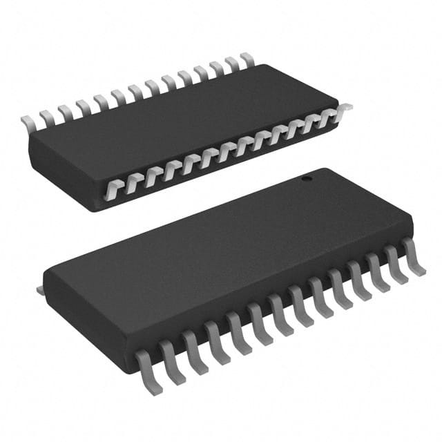
Encyclopedia Entry: 74ACT11652DWR
Product Overview
Category
The 74ACT11652DWR belongs to the category of integrated circuits (ICs).
Use
This IC is commonly used in digital electronic systems for data transmission and processing.
Characteristics
- High-speed operation
- Low power consumption
- Wide operating voltage range
- Compatibility with various logic families
Package
The 74ACT11652DWR is available in a dual-width SOIC (Small Outline Integrated Circuit) package.
Essence
This IC serves as a multiplexer/demultiplexer, allowing for efficient data routing and selection within a digital system.
Packaging/Quantity
The 74ACT11652DWR is typically packaged in reels or tubes, with a quantity of 250 units per reel/tube.
Specifications
- Supply Voltage Range: 2.0V to 6.0V
- Input Voltage Range: 0V to VCC
- Output Voltage Range: 0V to VCC
- Operating Temperature Range: -40°C to +85°C
- Logic Family: ACT
Detailed Pin Configuration
The 74ACT11652DWR has a total of 56 pins, arranged as follows:
- Pin 1: A0
- Pin 2: A1
- Pin 3: A2
- Pin 4: A3
- Pin 5: A4
- Pin 6: A5
- Pin 7: A6
- Pin 8: A7
- Pin 9: A8
- Pin 10: A9
- Pin 11: A10
- Pin 12: A11
- Pin 13: A12
- Pin 14: A13
- Pin 15: A14
- Pin 16: A15
- Pin 17: OE1
- Pin 18: OE2
- Pin 19: GND
- Pin 20: Y0
- Pin 21: Y1
- Pin 22: Y2
- Pin 23: Y3
- Pin 24: Y4
- Pin 25: Y5
- Pin 26: Y6
- Pin 27: Y7
- Pin 28: Y8
- Pin 29: Y9
- Pin 30: Y10
- Pin 31: Y11
- Pin 32: Y12
- Pin 33: Y13
- Pin 34: Y14
- Pin 35: Y15
- Pin 36: VCC
- Pin 37: B0
- Pin 38: B1
- Pin 39: B2
- Pin 40: B3
- Pin 41: B4
- Pin 42: B5
- Pin 43: B6
- Pin 44: B7
- Pin 45: B8
- Pin 46: B9
- Pin 47: B10
- Pin 48: B11
- Pin 49: B12
- Pin 50: B13
- Pin 51: B14
- Pin 52: B15
- Pin 53: OE3
- Pin 54: OE4
- Pin 55: GND
- Pin 56: Y16
Functional Features
The 74ACT11652DWR offers the following functional features:
- 16-bit multiplexer/demultiplexer
- Independent output enable control for each group of eight channels
- Non-inverting outputs
- High-speed operation with minimal propagation delay
Advantages and Disadvantages
Advantages
- High-speed operation allows for efficient data transmission and processing.
- Wide operating voltage range provides flexibility in various digital systems.
- Low power consumption contributes to energy efficiency.
Disadvantages
- Limited number of channels (16) may not be sufficient for complex applications requiring a higher channel count.
- The dual-width SOIC package may not be suitable for space-constrained designs.
Working Principles
The 74ACT11652DWR operates based on the principles of multiplexing and demultiplexing. It routes and selects data signals from multiple input sources to desired output channels, or vice versa. The IC utilizes logic gates and flip-flops to achieve this functionality.
Detailed Application Field Plans
The 74ACT11652DWR finds application in various fields, including but not limited to: 1. Data communication systems 2.
Senaraikan 10 soalan dan jawapan biasa yang berkaitan dengan aplikasi 74ACT11652DWR dalam penyelesaian teknikal
Sure! Here are 10 common questions and answers related to the application of 74ACT11652DWR in technical solutions:
Q: What is the 74ACT11652DWR? A: The 74ACT11652DWR is a dual 8-bit to 16-bit multiplexer/demultiplexer integrated circuit (IC) commonly used in digital systems.
Q: What is the purpose of the 74ACT11652DWR? A: The IC is designed to route data between two 8-bit buses and a single 16-bit bus, allowing for efficient data transfer and selection in digital applications.
Q: What voltage levels does the 74ACT11652DWR support? A: The IC supports a wide range of voltage levels, typically operating at 5V, making it compatible with many digital systems.
Q: How many inputs and outputs does the 74ACT11652DWR have? A: The IC has 16 inputs and 8 outputs, allowing for versatile data routing and selection.
Q: Can the 74ACT11652DWR be used as a demultiplexer? A: Yes, the IC can be used as a demultiplexer by selecting the appropriate control signals to route data from the 16-bit bus to one of the two 8-bit buses.
Q: What is the maximum frequency at which the 74ACT11652DWR can operate? A: The IC can operate at frequencies up to 125 MHz, making it suitable for high-speed digital applications.
Q: Does the 74ACT11652DWR have any built-in error detection or correction features? A: No, the IC does not have any built-in error detection or correction features. It primarily focuses on data routing and selection.
Q: Can the 74ACT11652DWR be cascaded to increase the number of inputs or outputs? A: Yes, multiple ICs can be cascaded together to increase the number of inputs or outputs, allowing for scalability in larger digital systems.
Q: What is the power supply requirement for the 74ACT11652DWR? A: The IC typically requires a single 5V power supply for operation.
Q: Are there any specific precautions to consider when using the 74ACT11652DWR? A: It is important to ensure proper decoupling capacitors are used near the power supply pins to minimize noise and voltage fluctuations. Additionally, following the recommended operating conditions and timing specifications provided in the datasheet is crucial for reliable operation.
Please note that these answers are general and may vary depending on the specific application and requirements. Always refer to the datasheet and consult with technical experts for accurate information.


