

Encyclopedia Entry: 74ACT11543DW
Product Overview
Category
The 74ACT11543DW belongs to the category of integrated circuits (ICs).
Use
This IC is commonly used in digital electronic systems for various applications, including data processing, signal transmission, and control functions.
Characteristics
- High-speed operation: The 74ACT11543DW is designed to operate at high speeds, making it suitable for time-critical applications.
- Low power consumption: This IC is optimized for low power consumption, ensuring efficient energy usage.
- Wide voltage range: It can operate within a wide voltage range, allowing compatibility with different power supply levels.
- High noise immunity: The 74ACT11543DW exhibits high noise immunity, enabling reliable performance even in noisy environments.
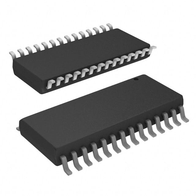
Package
The 74ACT11543DW is available in a dual in-line package (DIP) format. This package provides easy integration into circuit boards and facilitates soldering.
Essence
The essence of the 74ACT11543DW lies in its ability to process and manipulate digital signals efficiently, contributing to the overall functionality of electronic systems.
Packaging/Quantity
The 74ACT11543DW is typically packaged in reels or tubes, containing a specific quantity of ICs per package. The exact packaging and quantity may vary depending on the manufacturer and supplier.
Specifications
- Supply Voltage Range: 2V to 6V
- Logic Family: ACT
- Number of Inputs: 16
- Number of Outputs: 16
- Operating Temperature Range: -40°C to +85°C
- Propagation Delay: <10 ns
Detailed Pin Configuration
The 74ACT11543DW has a total of 48 pins, which are assigned specific functions as follows:
- Pin 1: Input A0
- Pin 2: Input A1
- Pin 3: Input A2
- Pin 4: Input A3
- Pin 5: Input A4
- Pin 6: Input A5
- Pin 7: Input A6
- Pin 8: Input A7
- Pin 9: Output Y0
- Pin 10: Output Y1
- Pin 11: Output Y2
- Pin 12: Output Y3
- Pin 13: Output Y4
- Pin 14: Output Y5
- Pin 15: Output Y6
- Pin 16: Output Y7
- Pin 17: Input B0
- Pin 18: Input B1
- Pin 19: Input B2
- Pin 20: Input B3
- Pin 21: Input B4
- Pin 22: Input B5
- Pin 23: Input B6
- Pin 24: Input B7
- Pin 25: Output Y8
- Pin 26: Output Y9
- Pin 27: Output Y10
- Pin 28: Output Y11
- Pin 29: Output Y12
- Pin 30: Output Y13
- Pin 31: Output Y14
- Pin 32: Output Y15
- Pin 33: GND (Ground)
- Pin 34: Enable (EN) Input
- Pin 35: Output Enable (OE) Input
- Pin 36: VCC (Positive Power Supply) 37-48: Not Connected (NC)
Functional Features
The 74ACT11543DW offers the following functional features:
- Data processing: It can process digital data inputs and generate corresponding outputs based on the internal logic circuitry.
- Signal transmission: The IC facilitates the transmission of digital signals between different components within an electronic system.
- Control functions: It can be used to implement various control functions, such as multiplexing, demultiplexing, and address decoding.
Advantages and Disadvantages
Advantages
- High-speed operation enables efficient data processing.
- Low power consumption contributes to energy efficiency.
- Wide voltage range allows compatibility with different power supply levels.
- High noise immunity ensures reliable performance in noisy environments.
Disadvantages
- Limited number of inputs and outputs may restrict its application in complex systems.
- Requires proper handling and static discharge precautions during installation to prevent damage.
Working Principles
The 74ACT11543DW operates based on a combination of digital logic gates and flip-flops. It receives input signals, processes them using internal logic circuits, and generates corresponding output signals based on the applied control functions. The IC's high-speed operation is achieved through optimized transistor configurations and circuit design.
Detailed Application Field Plans
The 74ACT11543DW finds applications in various
Senaraikan 10 soalan dan jawapan biasa yang berkaitan dengan aplikasi 74ACT11543DW dalam penyelesaian teknikal
Sure! Here are 10 common questions and answers related to the application of 74ACT11543DW in technical solutions:
Q: What is the 74ACT11543DW? A: The 74ACT11543DW is a dual octal transparent latch with 3-state outputs, commonly used in digital logic circuits.
Q: What is the purpose of the 74ACT11543DW? A: The purpose of this IC is to store and control the flow of data in digital systems by latching input signals and providing output signals.
Q: What is the maximum operating voltage for the 74ACT11543DW? A: The maximum operating voltage for this IC is typically 5.5V.
Q: How many latch units are there in the 74ACT11543DW? A: The 74ACT11543DW consists of two independent latch units, each capable of storing 8 bits of data.
Q: What is the output configuration of the 74ACT11543DW? A: The outputs of this IC are 3-state, meaning they can be actively driven high or low, or put into a high-impedance state.
Q: What is the propagation delay of the 74ACT11543DW? A: The propagation delay is the time it takes for the input signal to propagate through the latch and appear at the output. For the 74ACT11543DW, the typical propagation delay is around 7 ns.
Q: Can the 74ACT11543DW handle high-speed data transfers? A: Yes, this IC is designed to operate at high speeds and is suitable for applications that require fast data transfer rates.
Q: What is the power supply requirement for the 74ACT11543DW? A: The power supply voltage for this IC typically ranges from 4.5V to 5.5V.
Q: Can the 74ACT11543DW be used in both parallel and serial data transfer applications? A: Yes, this IC can be used in both parallel and serial data transfer applications, depending on the system requirements.
Q: What are some common applications of the 74ACT11543DW? A: Some common applications include data storage, address decoding, bus interfacing, and general-purpose digital logic circuits.
Please note that the answers provided here are general and may vary depending on specific datasheet specifications and application requirements.