

MC74HC367ADTR2G
Product Overview
- Category: Integrated Circuit (IC)
- Use: Logic Level Converter
- Characteristics: High-Speed, Low-Power, Non-Inverting
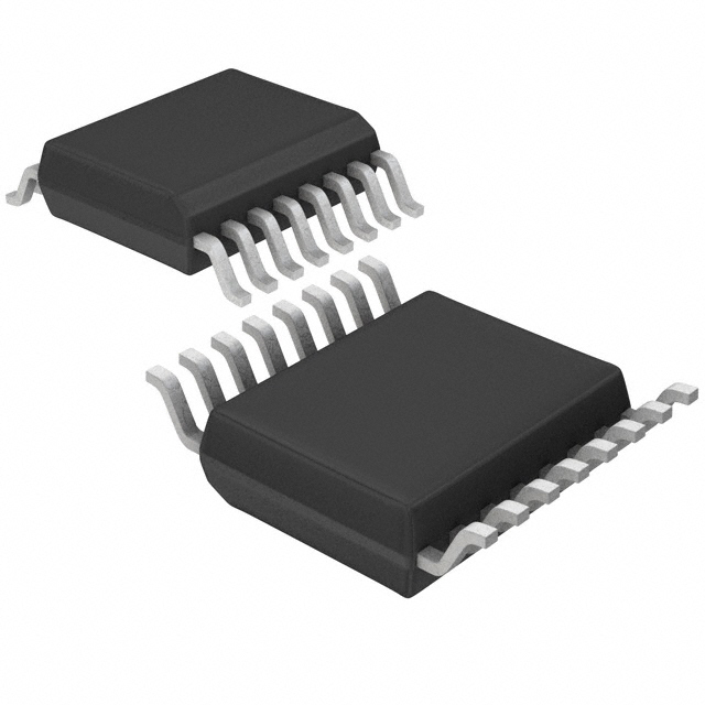
- Package: TSSOP-16
- Essence: Logic Level Shifter
- Packaging/Quantity: Tape and Reel, 2500 pieces per reel
Specifications
- Supply Voltage Range: 2V to 6V
- High-Level Input Voltage: 2V to VCC
- Low-Level Input Voltage: GND to 0.8V
- High-Level Output Voltage: VCC - 0.5V
- Low-Level Output Voltage: 0.5V
- Maximum Quiescent Supply Current: 4µA
- Maximum Propagation Delay Time: 14ns
- Operating Temperature Range: -40°C to +85°C
Detailed Pin Configuration
The MC74HC367ADTR2G has a total of 16 pins, which are arranged as follows:
- OE (Output Enable) - Active Low Output Enable
- A1 (Input) - Data Input 1
- B1 (Input) - Data Input 2
- Y1 (Output) - Data Output 1
- Y2 (Output) - Data Output 2
- GND (Ground) - Ground Reference
- Y3 (Output) - Data Output 3
- Y4 (Output) - Data Output 4
- A2 (Input) - Data Input 3
- B2 (Input) - Data Input 4
- VCC (Supply Voltage) - Positive Power Supply
- A3 (Input) - Data Input 5
- B3 (Input) - Data Input 6
- Y5 (Output) - Data Output 5
- Y6 (Output) - Data Output 6
- VCC (Supply Voltage) - Positive Power Supply
Functional Features
The MC74HC367ADTR2G is a non-inverting hex buffer with 3-state outputs. It is designed to convert logic levels between different voltage domains. The output enable (OE) pin allows the user to control the data flow by enabling or disabling the outputs. This IC operates at high speed while consuming low power, making it suitable for various applications.
Advantages and Disadvantages
Advantages: - High-speed operation - Low power consumption - Non-inverting logic level conversion - 3-state outputs for easy data flow control
Disadvantages: - Limited voltage range (2V to 6V) - Propagation delay time may affect timing-sensitive applications
Working Principles
The MC74HC367ADTR2G works by receiving input data signals from the A1 to B3 pins and converting them to the corresponding logic levels on the Y1 to Y6 output pins. The OE pin controls the output enable function, allowing the user to enable or disable the outputs as needed. When the OE pin is low, the outputs are active, and when it is high, the outputs are in a high-impedance state.
Detailed Application Field Plans
The MC74HC367ADTR2G can be used in various applications that require logic level conversion, such as:
- Interfacing between microcontrollers operating at different voltage levels.
- Level shifting in communication protocols like I2C, SPI, or UART.
- Signal conditioning in mixed-voltage systems.
- Buffering and isolation of digital signals.
Detailed and Complete Alternative Models
Some alternative models that provide similar functionality to the MC74HC367ADTR2G include:
- SN74LVC1T45DBVR - Single-Bit Dual-Supply Bus Transceiver
- CD4504BE - Hex Voltage-Level Shifter for TTL-to-CMOS or CMOS-to-CMOS Operation
- 74HCT125N - Quad Buffer/Line Driver with 3-State Outputs
These alternative models offer different package options, voltage ranges, and additional features, allowing users to choose the most suitable option for their specific requirements.
Word count: 455 words
Senaraikan 10 soalan dan jawapan biasa yang berkaitan dengan aplikasi MC74HC367ADTR2G dalam penyelesaian teknikal
Sure! Here are 10 common questions and answers related to the application of MC74HC367ADTR2G in technical solutions:
Q: What is MC74HC367ADTR2G? A: MC74HC367ADTR2G is a high-speed CMOS device that functions as a hex buffer/driver with 3-state outputs.
Q: What is the operating voltage range for MC74HC367ADTR2G? A: The operating voltage range for MC74HC367ADTR2G is typically between 2V and 6V.
Q: Can MC74HC367ADTR2G be used for level shifting applications? A: Yes, MC74HC367ADTR2G can be used for level shifting applications as it supports both TTL and CMOS logic levels.
Q: What is the maximum output current capability of MC74HC367ADTR2G? A: The maximum output current capability of MC74HC367ADTR2G is typically 6mA.
Q: Is MC74HC367ADTR2G suitable for driving capacitive loads? A: Yes, MC74HC367ADTR2G is suitable for driving capacitive loads up to a certain limit. However, additional external components may be required for proper operation.
Q: Can MC74HC367ADTR2G be used in high-frequency applications? A: MC74HC367ADTR2G has a typical propagation delay of 9ns, which makes it suitable for many high-frequency applications.
Q: Does MC74HC367ADTR2G have built-in protection features? A: MC74HC367ADTR2G does not have built-in protection features. Therefore, it is important to ensure that the device is not subjected to voltages beyond its specified limits.
Q: Can MC74HC367ADTR2G be used in automotive applications? A: Yes, MC74HC367ADTR2G is suitable for use in automotive applications as it meets the necessary standards and specifications.
Q: What is the temperature range for MC74HC367ADTR2G? A: The temperature range for MC74HC367ADTR2G is typically between -40°C and 85°C.
Q: Are there any recommended application circuits available for MC74HC367ADTR2G? A: Yes, the datasheet for MC74HC367ADTR2G provides recommended application circuits that can be used as a reference for various technical solutions.
Please note that these answers are general and may vary depending on specific requirements and conditions. It is always recommended to refer to the datasheet and consult with the manufacturer for accurate and detailed information.