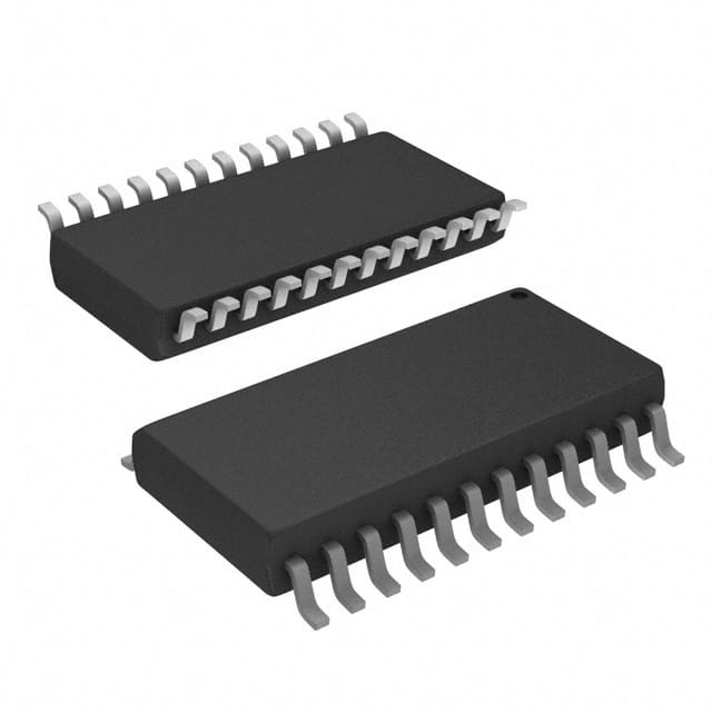
MC74ACT652DWG
Product Overview
- Category: Integrated Circuit (IC)
- Use: Digital Logic Level Shifter
- Characteristics: High-speed, Non-inverting, Octal Bus Transceiver
- Package: SOIC (Small Outline Integrated Circuit)
- Essence: This IC is designed to shift logic levels between different voltage domains in digital systems.
- Packaging/Quantity: Available in tape and reel packaging, with 2500 units per reel.
Specifications
- Logic Family: ACT
- Number of Channels: 8
- Input Voltage Range: 2.0V to 6.0V
- Output Voltage Range: 2.0V to 6.0V
- Propagation Delay Time: 7 ns (typical)
- Operating Temperature Range: -40°C to +85°C
Detailed Pin Configuration
The MC74ACT652DWG has a total of 24 pins, which are assigned as follows:
- A1: Channel A Data Input
- B1: Channel B Data Input
- C1: Channel C Data Input
- D1: Channel D Data Input
- E1: Channel E Data Input
- F1: Channel F Data Input
- G1: Channel G Data Input
- H1: Channel H Data Input
- OE*: Output Enable Input
- DIR: Direction Control Input
- VCC: Positive Power Supply
- GND: Ground
- A2: Channel A Data Output
- B2: Channel B Data Output
- C2: Channel C Data Output
- D2: Channel D Data Output
- E2: Channel E Data Output
- F2: Channel F Data Output
- G2: Channel G Data Output
- H2: Channel H Data Output
- NC: No Connection
- NC: No Connection
- NC: No Connection
- NC: No Connection
Functional Features
- Non-inverting bidirectional data transmission between two voltage domains.
- High-speed operation suitable for use in fast digital systems.
- 3-state outputs allow multiple devices to be connected to a common bus.
Advantages and Disadvantages
Advantages
- Provides level shifting capability for interfacing between different voltage domains.
- High-speed operation allows for efficient data transfer.
- 3-state outputs enable easy bus sharing among multiple devices.
Disadvantages
- Limited input and output voltage range (2.0V to 6.0V).
- Propagation delay time may affect timing-sensitive applications.
Working Principles
The MC74ACT652DWG operates by receiving data inputs from one voltage domain and transmitting them to another voltage domain. The direction of data transmission is controlled by the DIR pin. When the DIR pin is set to logic high, data is transmitted from the A1-H1 inputs to the A2-H2 outputs. Conversely, when the DIR pin is set to logic low, data is transmitted from the A2-H2 inputs to the A1-H1 outputs. The OE* pin is used to enable or disable the outputs.
Detailed Application Field Plans
The MC74ACT652DWG can be used in various applications where level shifting between different voltage domains is required. Some potential application fields include:
- Microcontroller interfacing with peripheral devices operating at different voltage levels.
- Communication systems involving multiple voltage domains, such as UART or SPI interfaces.
- Memory modules requiring level translation between different memory banks.
- Industrial automation systems with mixed voltage signal processing.
Detailed and Complete Alternative Models
- SN74ACT652: Similar octal bus transceiver from Texas Instruments.
- 74HCT652: Octal bus transceiver with TTL logic levels from NXP Semiconductors.
- CD74ACT652: Octal bus transceiver with Schottky-clamped TTL inputs from Texas Instruments.
These alternative models provide similar functionality and can be considered as alternatives to the MC74ACT652DWG based on specific requirements and availability.
Word count: 510 words
Senaraikan 10 soalan dan jawapan biasa yang berkaitan dengan aplikasi MC74ACT652DWG dalam penyelesaian teknikal
Sure! Here are 10 common questions and answers related to the application of MC74ACT652DWG in technical solutions:
Question: What is MC74ACT652DWG?
- Answer: MC74ACT652DWG is a specific model of an octal bus transceiver with 3-state outputs, commonly used in digital systems.Question: What is the purpose of MC74ACT652DWG?
- Answer: The purpose of MC74ACT652DWG is to enable bidirectional transfer of data between two buses or systems.Question: What voltage levels does MC74ACT652DWG support?
- Answer: MC74ACT652DWG supports TTL-compatible input and output voltage levels, typically ranging from 0V to 5V.Question: How many data lines can MC74ACT652DWG handle?
- Answer: MC74ACT652DWG can handle up to 8 data lines, making it suitable for applications requiring parallel data transfer.Question: Can MC74ACT652DWG be used in both synchronous and asynchronous systems?
- Answer: Yes, MC74ACT652DWG can be used in both synchronous and asynchronous systems, depending on the specific requirements of the application.Question: Does MC74ACT652DWG have any built-in protection features?
- Answer: MC74ACT652DWG has built-in diode clamps that provide protection against electrostatic discharge (ESD) events.Question: What is the maximum operating frequency of MC74ACT652DWG?
- Answer: The maximum operating frequency of MC74ACT652DWG is typically around 100MHz, making it suitable for high-speed data transfer applications.Question: Can MC74ACT652DWG be cascaded to handle more than 8 data lines?
- Answer: Yes, multiple MC74ACT652DWG devices can be cascaded together to handle more than 8 data lines if needed.Question: What is the power supply voltage range for MC74ACT652DWG?
- Answer: The power supply voltage range for MC74ACT652DWG is typically between 4.5V and 5.5V.Question: Are there any specific precautions to consider when using MC74ACT652DWG?
- Answer: It is important to ensure proper decoupling and bypassing of power supply pins, as well as following recommended PCB layout guidelines provided in the datasheet for optimal performance.
Please note that the answers provided here are general and may vary depending on the specific application and requirements. It is always recommended to refer to the datasheet and consult with technical experts for accurate and detailed information.


