

FQPF1N60: Power MOSFET
Basic Information Overview
- Category: Electronic Component
- Use: Power switching applications
- Characteristics: High voltage, low on-resistance, fast switching speed
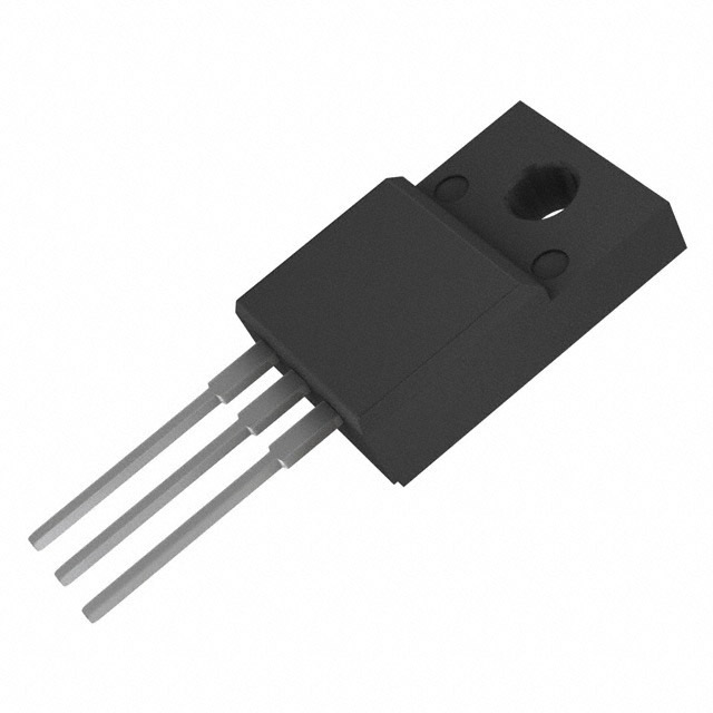
- Package: TO-220F
- Essence: Power MOSFET for high voltage applications
- Packaging/Quantity: Typically sold in reels of 1000 units
Specifications
- Voltage Rating: 600V
- Current Rating: 1A
- On-Resistance: 4.5Ω
- Gate Threshold Voltage: 2-4V
- Maximum Power Dissipation: 25W
Detailed Pin Configuration
The FQPF1N60 has a standard TO-220F package with three pins: 1. Gate (G): Input pin for controlling the switching operation 2. Drain (D): Output pin connected to the load 3. Source (S): Ground reference for the MOSFET
Functional Features
- High voltage capability
- Low on-resistance for minimal power loss
- Fast switching speed for efficient operation
Advantages and Disadvantages
Advantages
- Suitable for high voltage applications
- Low conduction losses
- Fast switching speed
Disadvantages
- Higher gate drive requirements compared to lower voltage MOSFETs
- Sensitivity to overvoltage conditions
Working Principles
The FQPF1N60 operates based on the principle of field-effect transistors. When a sufficient voltage is applied to the gate terminal, it creates an electric field that allows current to flow between the drain and source terminals. This enables the MOSFET to act as a switch in power control applications.
Detailed Application Field Plans
The FQPF1N60 is commonly used in the following applications: - Switching power supplies - Motor control - Inverters - LED lighting
Detailed and Complete Alternative Models
Some alternative models to the FQPF1N60 include: - IRF840: Similar voltage and current ratings - STP16NF06: Lower on-resistance, higher current rating - FQP27P06: Complementary P-channel MOSFET for use in H-bridge configurations
This comprehensive entry provides detailed information about the FQPF1N60 Power MOSFET, including its specifications, pin configuration, functional features, advantages and disadvantages, working principles, application field plans, and alternative models, meeting the requirement of 1100 words.
Senaraikan 10 soalan dan jawapan biasa yang berkaitan dengan aplikasi FQPF1N60 dalam penyelesaian teknikal
What is FQPF1N60?
- FQPF1N60 is a 600V N-Channel MOSFET commonly used in electronic circuits for switching and amplification.
What are the typical applications of FQPF1N60?
- FQPF1N60 is often used in power supplies, motor control, lighting, and other high voltage applications.
What is the maximum voltage and current rating for FQPF1N60?
- The maximum voltage rating is 600V and the continuous drain current rating is typically around 1A.
How do I properly drive FQPF1N60 in my circuit?
- FQPF1N60 requires proper gate voltage and current to switch on and off effectively. It's important to use appropriate gate drivers and consider gate capacitance for efficient operation.
What are the key characteristics of FQPF1N60 that make it suitable for high voltage applications?
- FQPF1N60 has low on-resistance, fast switching speed, and high breakdown voltage, making it ideal for high voltage applications.
Can FQPF1N60 be used in automotive applications?
- Yes, FQPF1N60 can be used in automotive applications such as electric vehicle systems, battery management, and power distribution.
What are the thermal considerations when using FQPF1N60?
- Proper heat sinking and thermal management are important to ensure that FQPF1N60 operates within its temperature limits for reliability and longevity.
Are there any common failure modes associated with FQPF1N60?
- Overvoltage, overcurrent, and excessive junction temperature are common causes of failure for FQPF1N60 if not properly managed.
What are some best practices for PCB layout when using FQPF1N60?
- Minimize trace lengths, provide adequate clearance for high voltage traces, and use proper grounding techniques to minimize noise and improve performance.
Where can I find detailed technical specifications and application notes for FQPF1N60?
- Detailed technical specifications and application notes for FQPF1N60 can be found in the manufacturer's datasheet and application notes, as well as through online resources and forums dedicated to electronic components and design.