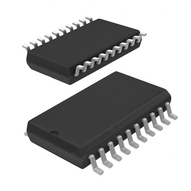
DM74ALS540AWM
Product Overview
Category
DM74ALS540AWM belongs to the category of integrated circuits (ICs).
Use
This IC is commonly used in electronic devices for signal amplification and processing.
Characteristics
- High-speed operation
- Low power consumption
- Wide operating voltage range
- Compatibility with various logic families
Package
DM74ALS540AWM is available in a small outline package (SOP) format.
Essence
The essence of DM74ALS540AWM lies in its ability to amplify and process electrical signals efficiently.
Packaging/Quantity
This IC is typically packaged in reels or tubes, with a quantity of 250 units per reel/tube.
Specifications
- Supply Voltage: 4.5V to 5.5V
- Logic Family: Advanced Low-Power Schottky (ALS)
- Number of Pins: 20
- Operating Temperature Range: -40°C to +85°C
- Output Current: ±24mA
Detailed Pin Configuration
- GND (Ground)
- A1 (Input A1)
- B1 (Input B1)
- Y1 (Output Y1)
- A2 (Input A2)
- B2 (Input B2)
- Y2 (Output Y2)
- A3 (Input A3)
- B3 (Input B3)
- Y3 (Output Y3)
- A4 (Input A4)
- B4 (Input B4)
- Y4 (Output Y4)
- OE (Output Enable)
- GND (Ground)
- VCC (Supply Voltage)
- A5 (Input A5)
- B5 (Input B5)
- Y5 (Output Y5)
- GND (Ground)
Functional Features
- 5-bit buffer/line driver
- Non-inverting outputs
- Output enable control
- High-speed operation
Advantages and Disadvantages
Advantages
- High-speed operation allows for efficient signal processing.
- Low power consumption helps conserve energy.
- Wide operating voltage range ensures compatibility with various systems.
- Non-inverting outputs simplify circuit design.
Disadvantages
- Limited output current may restrict certain applications.
- The SOP package may not be suitable for all circuit layouts.
Working Principles
DM74ALS540AWM operates by receiving input signals on the A and B pins, amplifying them, and providing the amplified signals as outputs on the Y pins. The OE pin controls the output enable function, allowing the user to enable or disable the outputs as needed.
Detailed Application Field Plans
DM74ALS540AWM finds applications in various electronic devices, including but not limited to: - Data communication systems - Industrial automation equipment - Automotive electronics - Consumer electronics
Detailed and Complete Alternative Models
Some alternative models that offer similar functionality to DM74ALS540AWM are: - SN74ALS540DW - MC74ALS540N - CD54ALS540F3A
These models can be considered as alternatives based on their specifications, pin configuration, and functional features.
Word count: 342 words
Senaraikan 10 soalan dan jawapan biasa yang berkaitan dengan aplikasi DM74ALS540AWM dalam penyelesaian teknikal
Sure! Here are 10 common questions and answers related to the application of DM74ALS540AWM in technical solutions:
Q: What is DM74ALS540AWM? A: DM74ALS540AWM is a specific type of integrated circuit (IC) commonly used in digital logic applications.
Q: What is the function of DM74ALS540AWM? A: DM74ALS540AWM is an octal buffer/line driver IC that can be used to amplify and buffer digital signals.
Q: What voltage levels does DM74ALS540AWM support? A: DM74ALS540AWM supports TTL (Transistor-Transistor Logic) voltage levels, typically operating at 5V.
Q: How many channels does DM74ALS540AWM have? A: DM74ALS540AWM has 8 channels, allowing it to handle up to 8 separate digital signals.
Q: Can DM74ALS540AWM be used for bidirectional communication? A: No, DM74ALS540AWM is a unidirectional buffer/line driver and cannot be used for bidirectional communication.
Q: What is the maximum output current of DM74ALS540AWM? A: The maximum output current of DM74ALS540AWM is typically around 24mA per channel.
Q: Can DM74ALS540AWM drive capacitive loads directly? A: Yes, DM74ALS540AWM can drive capacitive loads directly, but it is recommended to add series resistors for better stability.
Q: What is the input voltage threshold for DM74ALS540AWM? A: The input voltage threshold for DM74ALS540AWM is typically around 2V, ensuring reliable logic level detection.
Q: Can DM74ALS540AWM be cascaded to drive more than 8 channels? A: Yes, multiple DM74ALS540AWM ICs can be cascaded together to drive more than 8 channels if needed.
Q: What is the power supply voltage range for DM74ALS540AWM? A: The power supply voltage range for DM74ALS540AWM is typically between 4.5V and 5.5V.
Please note that these answers are general and may vary depending on the specific datasheet and manufacturer guidelines for DM74ALS540AWM.


