

IRFR120NTRLPBF
Product Overview
- Category: Power MOSFET
- Use: Switching applications in power supplies, converters, and motor control
- Characteristics: High voltage, low on-resistance, fast switching speed
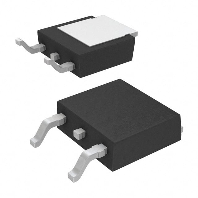
- Package: TO-252 (DPAK)
- Essence: Efficient power switching
- Packaging/Quantity: Tape & Reel, 2500 units per reel
Specifications
- Voltage Rating: 100V
- Continuous Drain Current: 9.7A
- On-Resistance: 0.12Ω
- Gate Threshold Voltage: 2V to 4V
- Power Dissipation: 2.5W
Detailed Pin Configuration
The IRFR120NTRLPBF has three pins: 1. Gate (G): Input for controlling the switching of the MOSFET 2. Drain (D): Connects to the positive supply voltage 3. Source (S): Connects to the load or ground
Functional Features
- Fast switching speed for improved efficiency
- Low on-resistance minimizes power loss
- High voltage rating for versatile applications
Advantages and Disadvantages
Advantages: - High voltage rating allows for diverse application use - Low on-resistance enhances energy efficiency - Fast switching speed improves overall performance
Disadvantages: - Sensitive to static electricity - Requires careful handling during assembly
Working Principles
The IRFR120NTRLPBF operates based on the principle of field-effect transistors. When a voltage is applied to the gate terminal, it creates an electric field that controls the flow of current between the drain and source terminals.
Detailed Application Field Plans
This MOSFET is commonly used in various applications such as: - Power supplies - DC-DC converters - Motor control circuits - Inverters
Detailed and Complete Alternative Models
- IRFR3709ZTRPBF: Similar specifications with a lower on-resistance
- IRFR9120TRL7PP: Higher voltage rating and higher continuous drain current
- IRFR024NTRL: Lower voltage rating and on-resistance for specific applications
Note: The alternative models listed above are just a few examples from a wide range of available alternatives.
This comprehensive entry provides detailed information about the IRFR120NTRLPBF, including its product overview, specifications, pin configuration, functional features, advantages and disadvantages, working principles, application field plans, and alternative models.
Senaraikan 10 soalan dan jawapan biasa yang berkaitan dengan aplikasi IRFR120NTRLPBF dalam penyelesaian teknikal
What is the maximum drain-source voltage rating of IRFR120NTRLPBF?
- The maximum drain-source voltage rating of IRFR120NTRLPBF is 100V.
What is the continuous drain current rating of IRFR120NTRLPBF?
- The continuous drain current rating of IRFR120NTRLPBF is 9.7A.
What is the on-state resistance (RDS(on)) of IRFR120NTRLPBF?
- The on-state resistance (RDS(on)) of IRFR120NTRLPBF is typically 0.085 ohms.
What is the gate threshold voltage of IRFR120NTRLPBF?
- The gate threshold voltage of IRFR120NTRLPBF typically ranges from 1V to 2V.
Can IRFR120NTRLPBF be used in high-frequency switching applications?
- Yes, IRFR120NTRLPBF can be used in high-frequency switching applications due to its fast switching characteristics.
What is the operating temperature range of IRFR120NTRLPBF?
- IRFR120NTRLPBF has an operating temperature range of -55°C to 175°C.
Is IRFR120NTRLPBF suitable for use in power management circuits?
- Yes, IRFR120NTRLPBF is suitable for use in power management circuits due to its low on-state resistance and high current handling capability.
Does IRFR120NTRLPBF require a heat sink for certain applications?
- Depending on the specific application and power dissipation, IRFR120NTRLPBF may require a heat sink to maintain optimal operating temperatures.
What are some common applications for IRFR120NTRLPBF?
- Common applications for IRFR120NTRLPBF include motor control, DC-DC converters, LED lighting, and power supplies.
What are the key advantages of using IRFR120NTRLPBF in technical solutions?
- The key advantages of using IRFR120NTRLPBF include low on-state resistance, high current handling capability, and suitability for high-frequency switching applications.